 |
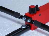
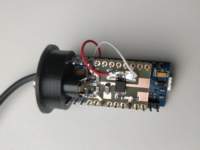
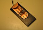
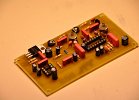
I build another ARDF receiver, again with the beloved DF1FO digital design. This time a 2 meter SMD type. All parts where bought at Uwe DL8UWE who sells the PCB with programmed processor a CNC't and drilled PCB housing and some dificult to get parts. He also provides a link to Reichelt electronicparts shop for al other parts needed to compleet the design. If you try to build this be prepared to design and invent your sollutions as this is not a compleet building package. I would not qualify this as a beginners project. But there are many pictures of designs online avaiable including my attempt here. As i own a 3D printer some parts are designed and printed giving the receiver a nice look. Also i changed the antenna design from what Uwe is suppling to the design i have been using with my other 2M receivers for years now, this means the reflector is placed furter back en the director is closer to the dipole. I believe this is called the 'russian' design, see the photo gallery for the details. | 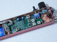 |
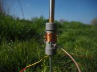 |
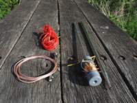
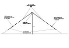
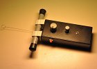
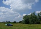
Telescopic antenna 40-10 meter 5.6 meter is more then long enough to make a fullsized 1/4 vertical for 20 meter, but i wanted also 40 meter and 30 meter so a base unit with groundstake and loading coil was made. An aligator clip is used to select the desired band. I use 2 counterpoise wires from some wire i had laying arround, one is 7.5m and the other 5m long. On the higer bands the aligator clip is connected to the center of the BNC bypassing the coil and tuning is done by lengthening and shortening the whip antenna Achieved SWR: 40m = 1.64, 30m = 1.42, 20m = 1.2, 17m = 1.24, 15m = 1.31 and 10m = 1.55, al very acceptable |
 |
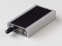 |
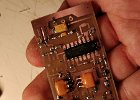
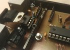
After buiding the compact keyer i now made a more feature-rich keyer , this version has a speedpotmeter, an audio beeper, programmable macro buttons and PTT output. But it is still very small and also supports Winkey2 emulation. For those who want to build it you can download a PDF file with the PCB layout here. All components are soldered on one side of the PCB board SMD style, the copper layer on the other side is un-ecthed and acts as shielding. The transparant acrylic front/backplate are custom made. The are two jumpers on the PCB, JP1 to switch on/off the buzzer (not nessasery since this can also be done in software). JP2 has to be on to make Winkey2 emulation work but has te removed to program the Arduino. Parts list Arduino: Nano Housing: Bopla ELPU 620 57.5x100mm PCB doublesided: Bungard FR4 1.5mm 56x100mm IC1,IC2: Optocoupler LTV 357T-SMD C1,C2,C5,C6,C7,C8: 10nF 0805 C3,C4: 10uF tantaal 1206 R1: 10K 0805 R2,R3,R4: 1K 0805 R5,R6: 470E 0805 R7,R8: 680E 0805 D1: LED red 0805 D2: LED green 0805 L1,L2: 10uH 0805 P1: 100K RK097N S0,S1,S2,S3: 6x6mm PCB tactile button (7mm) Buzzer: DMT-1206 |
 |
 |
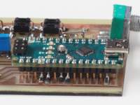
A small and compact CW keyer based on a Arduino Nano emulating Winkey2. K3NG has writing an opensource CW keyer that can emulate almost 100% of the winkey2 instructionset using the Arduino platform The goal was to make it as compact as possible, so no speedpot or buttons or other fancy things. Just a small keyer that can work with all logging software supporting the Winkey2 protocol. |
 |
 |
ROX2-T 2 meter ARDF SMD version But i was very happy with my housing design for the ROX2-X so i designed a SMD version of the ROX2-T at exact the same size as the ROX2-X and is switched them out, so now my housing contains a ROX2-T. |
 |
 |
Modding the QRP labs QCX CW Tranceiver In an effort to make it evenmore excellent then it already is i did a few mods. 1. As i already have a KX3 with paddle, i 3d printed a bracket to mount the KXPD3 paddle to the QCX, for this had to move the headphones jack (yes i am lefthanded) 2. I joint 4 Li-ion cells to a 4S battery with nominal voltage of 14.8 Volt (cell type 103040, 30x40x10mm, 1200mAh, 3.7V) it fits inside the housing underneath the PCB. i put a thin sheet of insulating foam between battery and PCB keeping the batterypack firmly in place. 3. At the GPS connector location a made a 6Pin connector with one pin blocked so i can't put the charging connecter in wrong, now i can balance charge the individual li-ion cells. 4. I replaced the power connector with a 3.5mm stereo audiojack for the headphones. 5. I mounted a P-channel FET witch switches the power supply on/off by plugging in/out the headphones. The transceiver is now standalone and with 1 meter coax and a end-fed antenna using a FT82-43 transformer with 10 meter wire i now have a 5Watt 20mtr portable CW station weighing under 600 grams. As for battery life, it seems oke, but needs further testing. |
 |
 |
Portable LightWeight 6 band Antenna It is based of the well proven End-Fed principle using a FT140-43 toroid with a 1:7 turns ratio (2 turns primair and 14 turns secundair) creating a 1:49 impedance transformation. For the 30 and 17 meter band Anderson powerpole connectors are used to make the antenna resonant a these frequencies. The antenna is wel capable of handling powers of up to 100Watt. |
 |
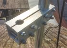 |
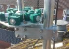
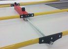
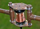
Hex Beam in front of mast mounting There is however one thing i don't like about Hexbeams, they are always mounted on top of the mast, but since i also like VHF i wanted to keep my 6/4/2 meter antenna's above the HF antenne. After some thinking i came up with the idea to mount the Hex beam halfway up in front of the mast using a (homemade) bracket. The bracket is made of aluminum 270mm long 80x80 mm square 5mm thick. 8 holes of 10mm where drilled in the sides for the bolds, a 60mm and 35mm hole was drilled in top for the mast and Hexbeam. Then the bar was cut in two. With this bracket the antenne is mounted rock sollid to the mast. As an extra i also used a smaller bracket to give the top of the Hex beam some extra support. I did no priore SWR test, but the SWR is fine on all bands. Click on the title of this post and you'll get the picture |
 |
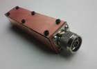 |
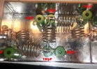
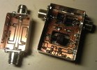
Because my preamp for 2 meter has much more gain then needed i build a RX bandpass filter to make it a bit easier for the receiver frontend. Since i only use it for DX-ing the filter is peaked around 144.3MHz. It has quite some attenuation in the passband with almost -5dB but this gives steep slopes. This however can be easily adjusted with the copper coupling wire. On the low side at 134MHz signals are already -28dB lower than the passband. And at 100MHz the attenuation is -65dB. On the high side at 154MHz -26dB is achieved and at 200MHz -56dB. My FT-897d is quite happy with this filter and overall reception is much less noisy and calmer. The frontend probably got overloaded by the preamp, though gain was set at a minimum (+14dB) | 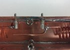 |
 |
DF1FO FJRX85 80-meter ARDF receiver |
 |
 |
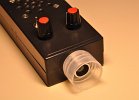
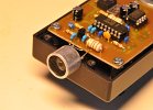
Because I heard good things about it I decided to build the ROX2-x 2Meter ARDF receiver as designed by Dave G3ZOI. It uses a different approach then I am used to, it has no “real” AM detector but uses the S-meter output of an FM receiver chip. This signal still has traces of the AM modulated fox transmitter so one can still hear the Morse code send by the fox. But the signal is also used to control a PLL tone generator which varies in pitch. The higher the tone the stronger the signal. It's a no nonsense design with only 2 controls, frequency and attenuation (tone hight). I tried to keep the receiver as light as possible and managed to keep it at about 370 Grams. | 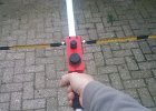 |
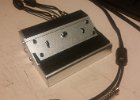 |
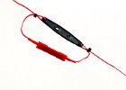
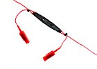
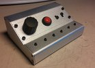
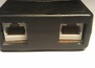
For using one headset with 2 tranceivers i build a switchbox, a single switch lets me select tranceiver A or B. Via 2 red RCA connectors it is possible to connect a footswitch and other (digital) PTT control . Also a sequencer is build in the lets me sequence PreAmp, PostAmp and TRX keying. This via black RCA connectors per transceiver 2 connectors. A switch lets me select no sequencing, 1 trap sequencing and 2 traps sequencing. The headset is connected via two 3.5mm jack connector on the side. | 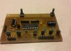 |
 |
300 Watt 144MHz lineair amplifier |
 |
 |
OE6GC ARDF80v6 80-meter ARDF receiver | 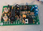 |
 |
DF1FO FJRX234 2-meter ARDF receiver | 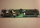 |
 |
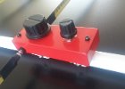
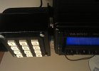
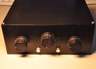
I've been using a winkey2 for a few years now and it is a briljant piece of hard/software by K1EL. However i never got arround making a neat case for it. Since i now have a 3D printer i was looking for thing that could be done better. I don't like the texture of housing that are completly printed in 3D so i did not opt for that. I ordered a goodlooking aluminum case from eBay. And used the 3D printer for a bracket so that te switches don't need a hole in the front plate. And also a support bracket for the pushbutton array. I think it has turned out well. The device has two outputs for connecting 2 transveivers and also two PTT outputs for controling prehipial devices. | 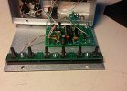 |
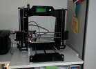 |
Geeetech Reprap Prusa I3 Pro X 3D Printer | 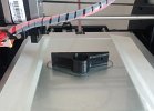 |
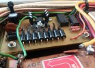 |
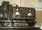
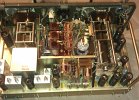
Here are a few pictures of the mods that are done to my Kenwood TL-922 amplifier. Some mods where done by a previous owner. These include the low voltage PTT circuit mod, dropping the PTT circuit from a whooping 100+ Volt and 30+ mA to a few volts and mA, making the amplifier suitable to be keyed by a modern transceiver. The ALC circuit was completely removed by a previous owner, i did not bother to rebuild it. This just means a bit more caution when operating the amplifier. Also direct grounding of the grid was done by a former owner. For safety and recommended by Fritz PA0FRI as a minimum modification for the TL-922. I installed a 1 Amp fuse in the high voltage circuit (microwave oven type, obtained for a few euro on eBay) and also added a 10 Ohm 10W glitch resistor in the high voltage circuit, this will protect the amplifier in a case of a short-circuit, random-oscillation or other mischief. When i bought the amplifier the antenna relay made some bad contact on receive sometimes. So i had to look for a solution. The good news is that the slow and noisy relay can be replaced by two relatively cheap but silent and fast vacuum-relays. Because of this i decided to make a few more mods to the amplifier. Again using the excellent site of Fritz PA0FRI as a guide, the BIAS circuit is converted to solid-state. And the STBY/ON AIR lights are now controlled by a reed-relay. This means that the other slow and noisy (bias) relay was also obsolete. RX/TX switching is now hyper fast and ultra silent. And finaly a solid-state relay was added to the mains circuit with a 10 Ohm 10W resistor to limit the initial inrush current. After about 100mSec the relay switches to bypass the 10 Ohm resistor. | 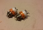 |
 |
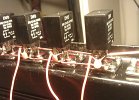
Lowpass filter with a cutoff frequency of 30MHz. Power handeling capabilities should be up to 2KiloWatt. The design can be found on the excellent site of Fritz PA0FRI who has many, many very intresting items on his site, a site well worth visiting. The capacitors are from eBay and rated at 2Kv (2x 100pF, 2x 82pF, 2x 150pF), the coils are made from 6mm2 tinned ground lead wire. SWR and attenuation is very acceptable trough out the passband, while at 100MHz ~50dB attenuation is achieve | 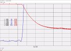 |
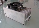 |
A 1000 Watt lowbudget dummyload. Using 2x 50 Ohm, 250 Watt resistors and 2x 50 Ohm, 250 Watt terminators. The signal is fed trough a 50 Ohm resistor to a 50 Ohm termination resistor. This creates a 100 Ohm path to ground, but since there are 2 of them parallel, resistance goes back to 50 Ohm again. This wil probably only work well under 30 MHz. The chip resistors where 4,5 euro a piece from eBay and the aluminum cooling blok was salvaged from a flea market for 8 euro. Making a total cost of 26.- euro. Not bad for a 1KW dummyload. | 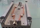 |
 |
Since i now have a linear amplifier on HF bands, a transverter on the 4 meter band and a preamp on 2 meters there was need for a sequencer. Since i use all these devices in a OR situation and not AND . i only needed one simple secuenced output and i decided to build it into my kenwood MC-50 desktop microphone. I use a 16F628A witch i had lying around. When the PTT is pushed the sequencer output is keyed directly , and after 50 milliseconds the transceiver is keyed. When the PTT is released the transceiver is keyed-down directly and the sequencer output is keyed-down after a 50 milliseconds delay. keying is done bij a 2N7000 for the transceiver, and by a IRF530 for the peripheral devices. The PIC processor is fed by the transceiver mic connector witch carriers +5V. I also made a small AND switch for safety, this makes it impossible to key the transceiver if the sequencer output is not keyed. | 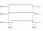 |
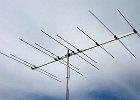 |
To use with my 4 meter transverter I bought a single boom Dualband EA5070-OWA9 from Wimo. Those are not cheap, but they are well made. It uses the "open sleeve" technique, so only the 6 meter dipole is fed. It is a 4 element Yagi on 50MHz and a 5 element on 70MHz. Here some pictures of how I put it together, A electrical box was placed at the center of the driven dipole to waterproof it and to install a current choke balun. | 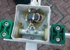 |
 |
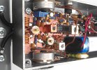
The XV4-40 is a 4 meter transverter designed and sold as kit by DF2FQ. It is all-mode and converts from the 10meter band to 4meter and back using a 41MHz SMD oscillator. Input power range is from 1mW to 8W depending on the input circuit. Output power is made by a Mitsubishi power module delivering about 25W Pep SSB and up to 40W in CW. Building it was very easy and the kit is well designed and very complete, including housing, BNC plugs and cooling. Alignment is pretty straight forward and there are no expensive device's needed. Made some great contacts with it including a QSO with EA8 on the second day i was on the air with it. A lot of fun kit for moderately experienced builder. I made some small modifications, i'am using a P-channel FET as reverse polarity protection. And fitted a DC power jack and RCA connector as PTT input. | 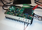 |
 |
Dummyload made of glass jar containing salt water, very low cost dummy load capable of handling a lot of power, (handles 400w effortlessly and can probably handle much more, i am unable to test this). SWR goes up in a steady line, but on 10 meter band still usable with 1:1.5. On 6 meter SWR has risen to 1:2 making it not very usable any more. I found that a little salt is enough, only half a teaspoon was sufficient to get as close to 50 ohm as possible over the complete range from 1 to 30 MHz. |
 |
 |
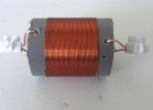
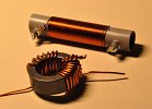
Broadband 1:1 Balun made from 3 bundled AM radio ferrite rods. I used 3 rods to increase power handling capabilities. The balun is made of 3 times 13 windings 1.4mm copper wire. | 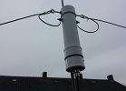 |
 |
For our small contest group i made 2 filters, one to block the 40,80 and 160 meter band and pass 20,15 and 10 meter band. Another filter to block 20,15 and 10 meter and pass 40,80 and 160 meter band. This way we can work/listen with 2 transceivers simultaneous. Since we are not planning on a multi-multi station set-up. This is a simple way to monitor other bands and quickly switch bands. | 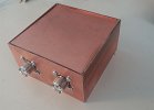 |
 |
4-way antenna switch made of junkbox parts. When no power is applied ANT-1 is connected to the TRX. I have a dummy load connected to ANT-1 so when powered off my TRX is always connected to the dummy load. Not used antenna's are grounded. | 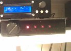 |
 |
Multiband dipole antenna for 80 meters, 40 meters and 15 meters. Only 2x 11 meter long. I was looking for a relative compact antenna for 80, 40 meters to be used during holidays. The antenna is tuned for the CW portion of the band. It is made from army field-telephone wire witch consists of 3 steel wires and 3 copper wires. Thus being strong with somewhat better conductance. I use a 12.5 meter long fibreglass pole from DX-Wire as a mast. Bandwidth on 80 is small witch is to be expected for such a short 80 meter dipole. However it works fine. You get 15 meter band as a bonus, but you need an antenna tuner to fine tune it. |
 |
 |
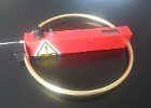
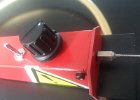
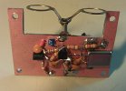
Relative simple 2 meter ARDF receiver designed by Rainer Flößer - DL5NBZ. The complete project can be downloaden from ardf.darc.de. It is a single super-heterodyne receiver with a 1.6MHz IF. The IF filtering is done by only one RC filter so selectivity is not very good. The receiver only has two controls, one for frequency and one for RF/LF gain. Some parts especially the coil where difficult to find, and i had to made some adjustments to de PCB board to fit a larger IF RC filter. However the receiver is quite sensitive and pretty directional. Until now i found every fox i ever hunted with it. | 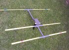 |
 |
DIY Domotica system using RS-485 Homebus Protocol |
 |
 |
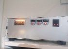
Yaesu FT897D standalone numeric Keypad Several options can be set by pressing a number while switching on the power of the transceiver. 1 = 4800 Bps, 2 = 9600 Bps, 3 = Audio beeps ON, 4 = Audio beeps OFF, 5 = Thru ON, 6 = Thru OFF With thru ON the CAT signal is passed thru to make it possible to connect additional CAT software. However this means the processor stays active and since it uses a 4MHz x-tal there might be some interference signals in the shortwave bands. Switching Thru OFF means the processor goes into sleep modus after sending a command. The x-tal oscillator is switched off in sleep modus. |
.jpg) |
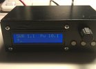 |
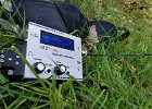
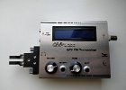
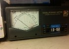
Digital SWR meter for HF/VHF and UHF |
 |
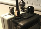 |
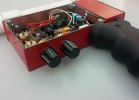
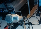
A simple method of making a attenuator witch can be used in combination with a regular hand-held. This is done by mixing the wanted signal with a local oscillator, and making the local oscilator level adjustable. Thus creating a dynamic range of more than 100dB, regardless of the poor shielding and limited S-meter range of most hand-helds. The mixing attenuator can be used for ARDF on any band the hand-held and antenna permit. but most likly in the VHF/UHF range. My design uses a 4MHz X-tal. Thus creating an offset of plus or minus 4 MHz witch one to best listen to depends on interference. |
 |
 |
Single paddle CW keyer made of double sided copper clad board. | 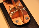 |
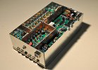 |
SDR complete transceiver for the short-wave bands, using a soundcard for IQ detection. Bandwidth 48/96/192 depending on the sound-card. frequency controlled via USB by a SI570 oscillator. And compatible with many SDR software (PowerSDR, LinRad, HDSDR a.o.) | 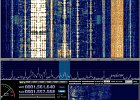 |
 |
Direct conversion receiver using a TCA440 designed by DL4CU (Bodo Schneider), check out his site |
 |
 |
Magnetic Loop antenna for 30/20/17/15 meters At the top a vacuum capacitor of 4 to 100pF made for max 5KV. Motor controlled via a 16F819 PIC processor with LCD for frequency readout.
|
 |
 |
Home-made antenna tuner in a Phi configuration, using Amidon T200-2 as coil, not suited for high power use since the plate separation is not very great. A second Amidon T200-2 is used to create a symmetric 1:4 output. | 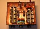 |
 |
End fed multi-band portable antenna Total length is about 12 meters and it does not need any radials. Mounted in a 12.5 meter fibre portable antenna pole it is ideal for portable use. It can easily be used on other bands by changing to another length of wire. |
 |
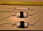 |
4-band End-fed portable antenna Total length is about 9 meters and it does not need any radials. Coax traps are used for 10 meter and 15 meter and a choke/loading coil for 20 and 40 meter bands. |
 |
 |
Enhanced TCA440 Bat sound detector designed by Bertrik Sikken, not really a HAM radio device, but it’s somewhat a radio, as it uses a TCA440 for converting 40KHz to a audible frequency,
It does this by the direct conversion method, it uses a 40KHz piezo transducer as microphone. Many thanks goes to Bertrik Sikken, and his excellent site on Bat-sound detection http://bertrik.sikken.nl/bat/index.html Print layout PDF Onderdelen lijst www.reichelt.de The piezo transducer did not quite do what i wanted, so i now use a electret microphone element. This works much better over a wide frequency range. The electret used is a Panasonic WM61a which has good characteristics in the ultrasonic range. The diagram is somewhat changed. Power supply for the electret is added, a highpass filter is added to prevent LF feedback, and the LM386 is given somewhat more gain. |
 |
 |
Zend-ontvanger: RT-3030/GRC-3030
Kristal ijkoscillator: SG-3007/GRC-3030
Voedingseenheid: DY-3030/GRC-3030
Aansluitkast: NZ20Z56
Dit geheel is gemonteerd op het draagrek N60Z830 welke weer met vier schokdempers op de montageplank N60Z831 is geschroefd.
|
 |